4. Setting up the tool
Before the Data Selector tool will function, it needs to be installed and configured. It is recommended that the configuration is carried out first, although the steps are interchangeable for the ArcGIS implementation.
4.1. Configuring the tool
The configuration is stored in an XML file called ‘DataSelector.xml’, and there are some differences in the contents of this file between the MapInfo and the ArcGIS implementations of the tool. Please ensure that you are using the correct XML file, examples of both of which can be found in the Appendix. Attributes and settings are presented as nodes (beginning with a start node, e.g. <example>, and finishing with an end note, e.g. <\example>), with the value for the setting held between the <value> and <\value> tag.
Caution
The name of the configuration file must be ‘DataSelector.xml’. The tool will not load if a different name is used.
The XML file can be edited in a text editor such as Notepad or Wordpad, or using a more feature rich XML editor such as as Sublime Text. The configuration file contains general attributes of the tool. The structure is roughly the same for both implementations of the tool.
Caution
It is important that the structure of the file is maintained as it is presented in the Appendix. Any changes to the structure may result in the Data Selector tool not loading, or not working as expected.
Once editing has been completed and the edits have been saved, it is recommended that the configuration file is opened using an internet browser such as Internet Explorer which will help highlight any editing errors – only if the structure of the file is valid will the whole file be displayed in the internet browser.
Note
It is recommended that the configuration file is kept in a central (network) location, so that all users use the same configuration. Additionally, in case of the MapInfo implementation of the tool, it is essential that the configuration file is kept in the same folder as the compiled version of the tool.
4.1.1. Special characters in XML
The characters &, < and > are not valid within values and, so in order to be used, must be escaped with XML entities as follows:
- <
- This must be escaped with
<entity, since it is assumed to be the beginning of a tag. For example,RecYear < 2010
- >
- This should be escaped with
>entity. It is not mandatory – it depends on the context – but it is strongly advised to escape it. For example,RecYear > 1980
- &
- This must be escaped with
&entity, since it is assumed to be the beginning of a entity reference. For example,TaxonGroup = 'Invertebrates - Dragonflies & Damselflies'
4.1.2. Setup for ArcGIS
4.1.2.1. General attributes for ArcGIS
The configuration file deals with a series of general attributes for the Data Selector tool. These general nodes specify where files are kept, which SQL Server to connect to, which SQL Server tables to make available and other overall settings. Details on these attributes (and their typical values where known) are given below. The list follows the order within which the attributes are found in the configuration file. This version of the configuration details is valid for the ArcGIS version 1.0.2 of the Data Selector tool.
- LogFilePath
- The folder to be used for storing log files. This folder must already exist.
- FileDSN
- The location of the File DSN that specifies to ArcGIS which SQL Server database to connect to.
- ConnectionString
- The connection string to establish an ADO connection to the source SQL Server database.
- DefaultExtractPath
- The default folder where output files will be stored. This can be overridden by the user when executing the tool.
- DefaultQueryPath
- The default folder where queries will be saved and loaded. This can be overridden by the user when executing the tool.
- DefaultFormat
- The default format of the output files to be created. Options available are ‘Geodatabase’, ‘Shapefile’, ‘CSV file’, ‘dBase file’ and ‘Text file’.
- DatabaseSchema
- The schema in the SQL Server database containing the source SQL tables. This is typically ‘dbo’.
- IncludeWildcard
- The Include wildcard for table names to list all the tables in SQL Server that can be selected by the user.
- ExcludeWildcard
- The Exclude wildcard for table names in SQL Server that should NOT be available for selection by the user. This enables temporary and user-specific tables to be hidden in the tool interface.
- RecMax
- Currently not used but must exist in XML.
- DefaultSetSymbology
- Currently not used but must exist in XML.
- LayerLocation
- Currently not used but must exist in XML.
- EnableSpatialPlotting
- Currently not used but must exist in XML.
Caution
All entries in the configuration file are case sensitive. Most common errors in the setting up of the tool are caused by using the incorrect case for entries.
4.1.3. Setup for MapInfo
4.1.3.1. General attributes for MapInfo
The configuration file deals with a series of general attributes for the Data Selector tool. These general nodes specify where files are kept, which SQL Server to connect to, which SQL Server tables to make available and other overall settings. Details on these attributes (and their typical values where known) are given below. The list follows the order within which the attributes are found in the configuration file. This version of the configuration details is valid for the MapInfo version 1.0.14 of the Data Selector tool.
- ToolTitle
- The title to use for the program in the MapInfo Tools menu.
- LogFilePath
- The folder to be used for storing log files. This folder must already exist.
- FileDSN
- The location of the File DSN that specifies which SQL Server database to connect to.
- DefaultExtractPath
- The default folder where output files will be stored. This can be overridden by the user when executing the tool.
- DefaultQueryPath
- The default folder where queries will be saved and loaded. This can be overridden by the user when executing the tool.
- DefaultFormat
- The default format of the output files to be created. Options available are ‘tab’, ‘shp’, ‘csv’ and ‘txt’.
- DatabaseSchema
- The schema in the SQL Server database containing the source SQL tables. This is typically ‘dbo’.
- TableListSQL
- The SQL statement used to list all the species tables in SQL Server that can be selected by the user.
- RecMax
- The maximum number of records what will be extracted in any one extract file.
- DefaultSymbologySet
- The default symbology set number that should be used for .tab files. The number corresponds to the order of the symbology sets defined in the MapInfoTables nodes. A value of ‘0’ (zero) sets the default to ‘<None>’ so that no symbology will be set by default.
- DefaultSpatialPlotting
The default for whether the SQL database tables can be spatially plotted. If ‘Yes’ the interface will display options for specifying how the data will plotted. If ‘No’ the options for specifying how the data will plotted are hidden in the user interface.
Note
Even if the selected SQL Server table is spatially enabled it is possible to re-plot the data (for example, using a different grid size or as points instead of polygons, or vice-versa)
- CoordinateSystem
- The spatial coordinate system to use for mapping when plotting data.
- DefaultSpatialColumns
This section defines the default SQL Server table columns to use for creating spatial data. It has the following entries:
- XColumn
- The default column containing the X co-ordinates (eastings). This can be overridden by the user when executing the tool.
- YColumn
- The default olumn containing the Y co-ordinates (northings). This can be overridden by the user when executing the tool.
- SizeColumn
- The default column containing the grid size (precision) to be plotted. This can be overridden by the user when executing the tool.
- DefaultPointsPrecision
- The default maximum precision for plotting polygons as points. Any records where the ‘SizeColumn’ is less than or equal to this value will be plotted as points. Any records where the ‘SizeColumn’ is greater than this value will be plotted as polygons. This can be overridden by the user when executing the tool.
- DialogSize
- Indicates the user interface dialog size for the tool. Options are ‘Norm’ or ‘Max’. It is generally recommended that ‘Max’ is used unless the dialog does not fit in the desktop.
4.1.3.2. Symbology attributes for MapInfo
- MapInfoTables
- This section defines the symbology sets available for applying to any MapInfo .tab outputs. It has the following entries:
All symbology sets are found within the <MapInfoTables> node. For each symbology set, which can be selected and applied to an output MapInfo .tab file, a new child node must be created. The node name (e.g. ‘SymbologySet1’) is not important but must be unique. A simplified example of a symbology set is shown in Fig. 4.1.

Fig. 4.1 Example of symbology set attributes configuration (MapInfo)
- Desc
- An attribute describing the symbology set. This will appear in the interface drop-down list.
- Symbology
- Each set contains only one child node
<Symbology>>under which multiple symbols can be specified. set Each symbol is specified between <Symbol> and </Symbol> tags and is defined by the following child nodes: - Clause
- The clause that defines the records which will be assigned this symbol. This can be left blank to apply the symbology to all records with the same <Object> type specified below.
- Object
- The object type that is symbolised using this symbol (e.g.
Region). Options are ‘Point’, ‘Line’ or ‘Region’. - Symbol
- The style to be used for the symbol. This attribute only applies to
Pointobjects. - Pen
- The style to be used for the symbol border (outline). This attribute applies to
Regionobjects. - Brush
The style to be used for the symbol infill. This attribute applies to
Regionobjects.Tip
In order to find the syntax for the Pen and Brush attribute, set the desired symbol for a polygon (region) layer through Options => Region style, then write
Print CurrentBorderPen()in the MapBasic window and hit enter. The printed pen definition (e.g.2,2,10526880) can be used in thePenattribute. Repeat withPrint CurrentBrush().
Caution
All entries in the configuration file are case sensitive. Most common errors in the setting up of the tool are caused by using the incorrect case for entries.
4.2. Setting up the SQL Server database
In addition to any SQL tables containing records to be extracted using the Data Selector tool, an auxiliary table must also be present in the SQL Server database in order for the tool to be able to select data from tables held in SQL Server. This table is as follows:
- Spatial_Tables table
This table contains information about any SQL data tables that may be used by the tool. The table has the following columns:
Table 4.1 Valid date and time format specifiers¶ Column Description TableName The name of the data table OwnerName The database owner, usually dboXColumn The name of the column holding the X coordinates of the record YColumn The name of the column holding the Y coordinates of the record SizeColumn The name of the column holding the grid size of the record (in metres) IsSpatial Bitwise column (1 = Yes, 0 = No) defining whether the table is spatially enabled SpatialColumn If the table is spatially enabled, the name of the geometry column (e.g. SP_GEOMETRY)SRID The name of the spatial reference system used to plot the records CoordSystem The coordinate system of the spatial data in the table SurveyKeyColumn The column containing the survey key for each record Note
The British National Grid SRID value is
Earth Projection 8, 79, "m", -2, 49, 0.9996012717, 400000, -100000 Bounds
(-7845061.1011, -15524202.1641) (8645061.1011, 4470074.53373)
Caution
This table must be filled out correctly for each SQL table that is available to the Data Selector tool.
4.3. Installing the tool
4.3.1. Installing in ArcGIS
Installing the tool in ArcGIS is straightforward. There are a few different ways it can be installed:
4.3.1.1. Installation through Windows Explorer
Open Windows Explorer and double-click on the ESRI Add-in file for the Data Selector tool (Fig. 4.2).

Fig. 4.2 Installing the Data Selector tool from Windows Explorer
Installation will begin after confirming you wish to install the tool on the dialog that appears (Fig. 4.3).

Fig. 4.3 Installation begins after clicking ‘Install Add-in’
Once it is installed, it will become available to add to the ArcGIS interface as a button (see CustomisingToolbarsArcGIS).
Note
In order for this process to work all running ArcMap sessions must be closed. The tool will not install or install incorrectly if there are copies of ArcMap running.
4.3.1.2. Installation from within ArcMap
Firstly, open the Add-In Manager through the Customize menu (Fig. 4.4).

Fig. 4.4 Starting the ArcGIS Add-In Manager
If the Data Selector tool is not shown, use the Options tab to add the folder where the tool is kept (Fig. 4.5). The security options should be set to the lowest setting as the tool is not digitally signed.

Fig. 4.5 The ‘Options’ tab in the ArcGIS Add-In Manager
Once the tool shows in the Add-In Manager (Fig. 4.6), it is available to add to the ArcGIS interface as a button (see CustomisingToolbarsArcGIS).

Fig. 4.6 The ArcGIS Add-In Manager showing the Data Selector tool
4.3.1.3. Customising toolbars
In order to add the Data Selector tool to the user interface, it needs to be added to a toolbar. It is recommended that this customisation is done inside a document, but it can be done so that the toolbar always appears in ArcGIS (see Fundamentals of Saving your Customizations for an explanation of how customisations are stored within ArcGIS).
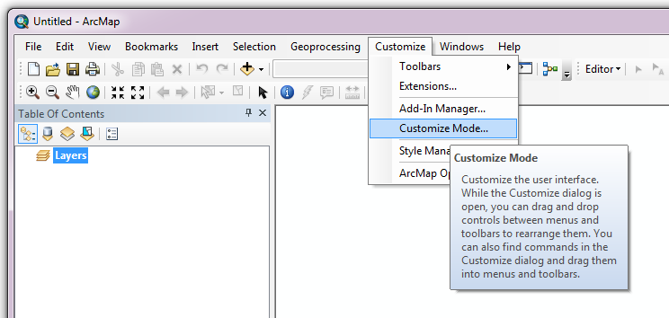
Fig. 4.7 Starting Customize Mode in ArcGIS
Customising toolbars is done through the Customize dialog, which can be started either through the Add-In Manager (by clicking Customize, see Fig. 4.6), or through choosing the ‘Customize Mode…’ option in the Customize Menu (Fig. 4.7).
Once this dialog is open, select or clear the check box ‘Create new toolbars and menus in the document’ as required in the Options tab (Fig. 4.8).

Fig. 4.8 Customising the document in ArcGIS
It is recommended that the button for the Data Selector tool is added to a new toolbar. Toolbars are created through the Toolbars tab in the Customize dialog, as shown in figures Fig. 4.9 and Fig. 4.10.

Fig. 4.9 Adding a new toolbar in ArcGIS
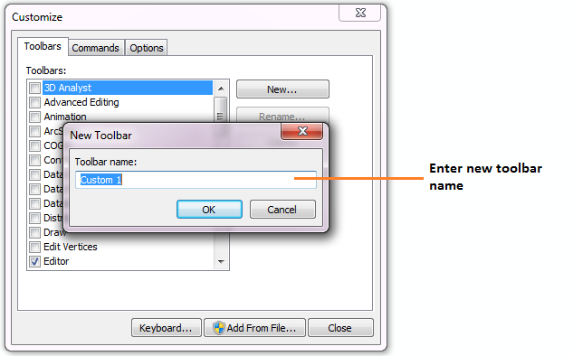
Fig. 4.10 Naming the new toolbar in ArcGIS
Once a new toolbar is created and named, it is automatically added to the ArcMap interface as well as to the Customize dialog (Fig. 4.11. In this case the toolbar was named ‘TestToolbar’).

Fig. 4.11 New toolbar added to the ArcGIS Interface
As a final step the Data Selector tool is added to the toolbar. This is done from the Command tab in the Customize dialog (Fig. 4.12). Click on Add-In Controls and the Data Selector tool will be shown in the right-hand panel.

Fig. 4.12 Finding the Data Selector tool in the add-in commands
To add the tool to the toolbar, simply drag and drop it onto it (Fig. 4.13). Close the Customize dialog and save the document. The Data Selector tool is now ready for its final configuration and first use.

Fig. 4.13 Adding the Data Selector tool to the new toolbar
In order to function, the tool needs to know the location of the XML configuration file. The first time the tool is run, or whenever the configuration file is moved, a dialog will appear asking for the folder containing the XML file (Fig. 4.14). Navigate to the folder where the XML file is kept and click OK. If the XML file is present and its structure is correct, the Data Selector form will be shown. Even if the tool is not run at this time, the location of the configuration file will be stored for future use.

Fig. 4.14 Locating the configuration file folder
4.3.2. Installing in MapInfo
To install the tool in MapInfo, make sure that the configuration of the XML file as described above is complete, that the XML file is in the same directory as the tool MapBasic application (.MBX). Then, open Tool Manager in MapInfo by selecting Tools --> Tool Manager... in the menu bar (Fig. 4.15).
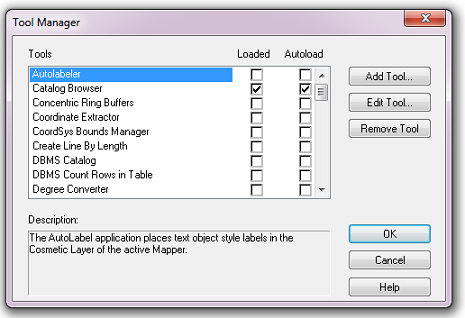
Fig. 4.15 The Tool Manager in MapInfo 12 or earlier
In the Tool Manager dialog, click Add Tool…, then locate the tool using the browse button ... on the Add Tool dialog (Fig. 4.16). Enter a name in the Title box (e.g. ‘DataSelector’), and a description if desired. Then click Ok to close the Add Tool dialog.

Fig. 4.16 Adding a tool in Tool Manager
The tool will now show in the Tool Manager dialog (Fig. 4.17) and the Loaded box will be checked. To load the tool automatically whenever MapInfo is started check the AutoLoad box. Then click Ok to close the Tool Manager dialog.

Fig. 4.17 The Data Selector tool is loaded
The tool will now appear as a new entry in the Tools menu (Fig. 4.18).

Fig. 4.18 The Data Selector tool menu
Note
The name that will appear in the Tools menu is dependent on the ToolTitle value in the configuration file, not the name given when adding the tool using the Tool Manager.